


Features and applications
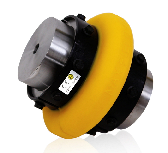
Characteristics of the MAX FIELD® COUPLING
- Designed for hot and humid environment and the material is superior than the standard coupling of MAX DYNAMIC®
- Torque ratings and torsional stiffness are higher than the standard coupling of MAX DYNAMIC®
- Facility protection for twirl, twist, impact, and abrasion.
- Very simple replacement and maintenance without any oil or grease.
- Very simple replacement without the separation of motor or connector on the related line due to its simple structure.
- Possible for the dissimilar connection and assembly with the same hub.
- Polyurethne based for good water and chemical resistance.
- Highest flexible elasticity on run.
- Less noise
Apllication
- AGITATORS
- BLOWERS
- COMPRESSORS
- CONVEYORS
- CRANES & HOISTS
- ELEVATORS
- FANS
- GENERATORS
- PUMPS
- BREWERY & DISTILLING
- FOOD INDUSTRY
- LUMBER INDUSTRY
- PULP & PAPER MILL
- RUBBER INDUSTRY
- STEEL INDUSTRY
- TEXTILE INDUSTRY
- AGGREGATE PROCESSING CEMENT
Specifications
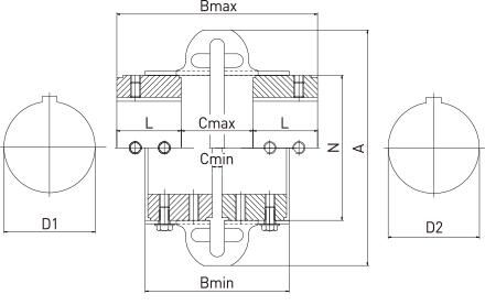
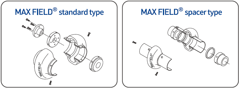
Standard Type
| MAX FIELD® coupling no. |
Tn (Nm) |
N Max. (rpm) |
Bore | A | B | C | L | N | Weight | |||
|---|---|---|---|---|---|---|---|---|---|---|---|---|
| D1 | D2 | min. | max. | min. | max. | kg | ||||||
| F-110 | 64 | 5,400 | 10 | 38 | 110 | 96 | 128 | 8 | 52 | 38 | 60 | 0.474 |
| F-125 | 106 | 5,400 | 10 | 48 | 120 | 97 | 130 | 8 | 52 | 38 | 70 | 0.550 |
| F-130 | 170 | 5,100 | 11 | 55 | 131 | 95 | 131 | 7 | 49 | 41 | 80 | 0.700 |
| F-150 | 256 | 4,800 | 11 | 65 | 150 | 111 | 159 | 9 | 57 | 51 | 95 | 1.020 |
| F-170 | 312 | 4,800 | 11 | 65 | 168 | 111 | 159 | 9 | 57 | 51 | 95 | 1.196 |
| F-190 | 420 | 4,600 | 19 | 75 | 190 | 113 | 161 | 7 | 57 | 52 | 117 | 1.526 |
| F-215 | 670 | 4,300 | 19 | 80 | 216 | 132 | 192 | 11 | 64 | 64 | 140 | 2.506 |
| F-245 | 970 | 4,100 | 19 | 95 | 245 | 136 | 203 | 8 | 73 | 65 | 171 | 3.080 |
| F-290 | 1,450 | 3,900 | 27 | 110 | 290 | 154 | 240 | 8 | 94 | 73 | 215 | 4.500 |
| F-365 | 3,300 | 3,600 | 35 | 127 | 365 | 200 | 311 | 20 | 131 | 90 | 235 | 11.800 |
| F-425 | 5,700 | 2,000 | 35 | 155 | 425 | 247 | 361 | 19 | 133 | 114 | 286 | 14.800 |
| F-460 | 6,400 | 2,000 | 48 | 165 | 460 | 267 | 380 | 19 | 132 | 124 | 302 | 17.200 |
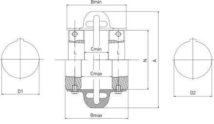
Spacer Type
| MAX FIELD® coupling no. |
Tn (Nm) |
N Max. (rpm) |
Bore | A | B | C | L | N | Weight | |||
|---|---|---|---|---|---|---|---|---|---|---|---|---|
| D1 | D2 | min. | max. | min. | max. | kg | ||||||
| FS-110 | 64 | 4,300 | 10 | 38 | 110 | 180 | 213 | 41 | 137 | 38 | 60 | 0.764 |
| FS-125 | 106 | 4,300 | 10 | 48 | 120 | 187 | 220 | 52 | 144 | 38 | 70 | 0.920 |
| FS-130 | 170 | 4,200 | 11 | 55 | 131 | 179 | 214 | 49 | 132 | 41 | 80 | 1.130 |
| FS-150 | 256 | 4,000 | 11 | 65 | 150 | 232 | 276 | 57 | 174 | 51 | 95 | 1.760 |
| FS-170 | 312 | 4,000 | 11 | 65 | 168 | 232 | 276 | 57 | 174 | 51 | 95 | 1.940 |
| FS-190 | 420 | 3,900 | 19 | 75 | 190 | 232 | 278 | 57 | 174 | 52 | 117 | 2.500 |
| FS-215 | 670 | 3,800 | 19 | 80 | 216 | 248 | 309 | 57 | 181 | 64 | 140 | 4.100 |
| FS-245 | 970 | 3,700 | 19 | 95 | 245 | 256 | 323 | 66 | 193 | 65 | 171 | 5.180 |
| FS-290 | 1,450 | 3,600 | 27 | 110 | 290 | 312 | 401 | 72 | 255 | 73 | 215 | 8.540 |
| FS-365 | 3,300 | 2,600 | 35 | 127 | 365 | 318 | 428 | 76 | 250 | 90 | 235 | 15.440 |
| FS-425 | 5,700 | 1,800 | 35 | 155 | 425 | 318 | 478 | 68 | 250 | 114 | 286 | 19.320 |
| FS-460 | 6,400 | 1,800 | 48 | 165 | 460 | 318 | 498 | 67 | 250 | 124 | 302 | 22.080 |
Taper-Lock Bushed Standard Type
| MAX FIELD® coupling no. |
Tn (Nm) |
N Max. (rpm) |
Bore | A | B | C | L | N | Bush No. |
|||
|---|---|---|---|---|---|---|---|---|---|---|---|---|
| D1 | D2 | min. | max. | min. | max. | |||||||
| F-110 | 64 | 5,400 | 10 | 38 | 110 | 96 | 96 | 42 | 50 | 22.3 | 60 | 1108 |
| F-125 | 106 | 5,400 | 10 | 48 | 120 | 97 | 97 | 42 | 50 | 22.3 | 70 | 1108 |
| F-130 | 170 | 5,100 | 11 | 50 | 131 | 98 | 108 | 36 | 56 | 25.4 | 80 | 1310 |
| F-150 | 256 | 4,800 | 11 | 65 | 168 | 112 | 118 | 54 | 66 | 25.4 | 95 | 1610 |
| F-170 | 312 | 4,800 | 11 | 65 | 168 | 112 | 118 | 54 | 66 | 25.4 | 95 | 1610 |
| F-190 | 420 | 4,600 | 19 | 75 | 190 | 116 | 124 | 50 | 60 | 31.8 | 117 | 2012 |
| F-215 | 670 | 4,300 | 19 | 80 | 216 | 134 | 157 | 45 | 68 | 44.5 | 170 | 2517 |
| F-245 | 970 | 4,100 | 19 | 95 | 245 | 136 | 170 | 44 | 69 | 50.8 | 171 | 3020 |
| F-290 | 1,450 | 3,900 | 27 | 110 | 290 | 152 | 188 | 40 | 87 | 50.8 | 215 | 3020 |
| F-365 | 3,300 | 3,600 | 35 | 127 | 365 | 220 | 310 | 18 | 130 | 90.0 | 235 | 3535 |
| F-425 | 5,700 | 2,000 | 35 | 155 | 425 | 247 | 335 | 44 | 132 | 101.6 | 286 | 4040 |
| F-460 | 6,400 | 2,000 | 48 | 165 | 460 | 266 | 360 | 38 | 132 | 114.3 | 302 | 4545 |
Taper-Lock Bushed Spacer Type
| MAX FIELD® coupling no. |
Tn (Nm) |
N Max. (rpm) |
Bore | A | B | C | L | N | Bush No. |
|||
|---|---|---|---|---|---|---|---|---|---|---|---|---|
| D1 | D2 | min. | max. | min. | max. | |||||||
| FS-110 | 64 | 5,400 | 10 | 38 | 110 | 180 | 180 | 76 | 135 | 22.3 | 60 | 1108 |
| FS-125 | 106 | 5,400 | 10 | 48 | 120 | 187 | 187 | 87 | 142 | 22.3 | 70 | 1108 |
| FS-130 | 170 | 5,100 | 11 | 55 | 131 | 180 | 184 | 70 | 134 | 25.4 | 80 | 1310 |
| FS-150 | 256 | 4,800 | 11 | 65 | 150 | 232 | 232 | 93 | 181 | 25.4 | 95 | 1610 |
| FS-170 | 312 | 4,800 | 11 | 65 | 168 | 232 | 232 | 93 | 181 | 25.4 | 95 | 1610 |
| FS-190 | 420 | 4,600, | 19 | 75 | 190 | 233 | 240 | 87 | 176 | 31.8 | 117 | 2012 |
| FS-215 | 670 | 4,300 | 19 | 80 | 216 | 248 | 262 | 90 | 173 | 44.5 | 140 | 2517 |
| FS-245 | 970 | 4,100 | 19 | 95 | 245 | 256 | 278 | 86 | 176 | 50.8 | 171 | 3020 |
| FS-290 | 1,450 | 3,900 | 27 | 110 | 290 | 312 | 347 | 131 | 245 | 50.8 | 215 | 3020 |
| FS-365 | 3,300 | 3,600 | 35 | 127 | 365 | 318 | 428 | 44 | 250 | 90.0 | 235 | 3535 |
| FS-425 | 5,700 | 2,000 | 35 | 155 | 425 | 318 | 453 | 44 | 250 | 101.6 | 286 | 4040 |
| FS-460 | 6,400 | 2,000 | 48 | 165 | 460 | 318 | 478 | 38 | 250 | 114.3 | 302 | 4545 |
Choosing of appropriate couplings
-
1. How to choose Type :
Coupling type depends on the application and the opreating conditions.
Please see the table on page 8 and then choose the most suitable couplings.
(Notice: Positive engagement for lifting motion only) -
2. How to calculate the nominal torque Ta(Nm) of the driven machine.
Ta = 9550 x kw/n
(kW = driven machine, n = speed(min-1)) -
3. How to determine the service factor(Sf)
Please see the table in each catalogue.
Please chech whether below.- if the driven machine is an internal combustion engine that has over 20% of the torque fluctuation, read page 10.
- if the driving speed is nearly critical speed, please ask the person in charge.
- if the ambient temperature is over 60 degrees Celsius, please ask the person in charge.
- if the number of starts per hour is over 10 times, please ask the person in charge.
-
4. How to calculate the equivalent torque Teq(Nm)
Teq = Ta x (Sf + St)
Ta = torque(Nm) of the driven machine, Sf = service factor, St = Temperature service factor (see no. 8 blelow) -
5. Be the nominal torque of the coupling(TN) bigger than Teq
Please check dimensional drawings
TN ≥ Teq
TN = norminal torque of the coupling (refer to dimensional drawings) -
6. Checking of the selection
Tmax = the maximal peak torque
Tmax ≤ 2 x TN -
7. How to check the bores
If the diameters of the shaft are known, please check coincident bores are available if possible.
When the couplings need bore and keyway, please be advised the precise dimensions and tolerances.
Alignment
Maximum Misalignment-mm/inch
| Coupling Size | 110 | 125 | 130 | 150 | 170 | 190 | 215 | 245 | 290 | 365 | 425 | 460 |
|---|---|---|---|---|---|---|---|---|---|---|---|---|
| △ Ka max(mm)Angular | 4.24º | 4.94º | 5.64º | 6.64º | 6.64º | 6.13º | 7.33º | 93º | 11.23º | 8.22º | 102º | 9.51.8º |
| △ Kr max(mm)Radial | 1.6 | 1.6 | 1.6 | 1.6 | 1.6 | 2.4 | 2.4 | 2.4 | 2.4 | 3.2 | 3.2 | 3.2 |
| △ Ka max(in)Angluar | 0.1654º | 0.1934º | 0.224º | 0.264º | 0.0264º | 0.243º | 0.2873º | 0.3543º | 0.4413º | 0.3232º | 0.3942º | 0.3741.8º |
| △ Kr max(in)Radial | 0.063 | 0.063 | 0.063 | 0.063 | 0.063 | 0.095 | 0.095 | 0.095 | 0.095 | 0.126 | 0.126 | 0.126 |
STEP 1.
STEP 2.

STEP 3.

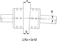
Alignment
Measure each misalignment value and calculate the ratio of this value by using the maximum indicated value.
The sum of these ratios must be less than 1:
dr/△ r + dr/△ α < 1
- dr = measured radial misalignment value
- △ r = max.radial misalignment value
- d α = measured angular misalignment value
- △ α = max. angular misalignment value
Correct alignment if this sum is greater than 1.
| Size | F-110 | F-125 | F-130 | F-150 | F-170 | F-190 | F-215 | F-245 | F-290 | F-365 | F-425 | F-460 |
|---|---|---|---|---|---|---|---|---|---|---|---|---|
| (a-b)mm | 4.2 | 4.9 | 5.6 | 6.6 | 6.6 | 6.1 | 7.3 | 9 | 11.2 | 8.2 | 10 | 9.5 |
| △ r | 1.6 | 1.6 | 1.6 | 1.6 | 1.6 | 2.4 | 2.4 | 2.4 | 2.4 | 3.2 | 3.2 | 3.2 |


Service Factors
Service Factors chart
| Load Conditions | Service Factors |
|---|---|
| Continuous driving Loads vary only slightly | 1 |
| Applied torque varies during operation | 1.5 |
| Applied torque varies during operation, 'stop' and 'go' cycles are encountered often. | 2 |
| Small shock and radical torque variations are applied. | 2.5 |
| Heavy shock or normal reversing drives are loaded | 3 |
| Reversing torque load doesn't always imply reversal of roatation | ask person in charge |
Service(Safety) Factor for each running part
| General Applications | Service Factor | Industrial Applications | Service Factor |
|---|---|---|---|
| AGITATORS | 1.5 - 2.0 | Aggregate Processing Cement | 2.0 - 3.0 |
| BLOWERS | 1.0 - 1.5 | Bewery & Distilling | 1.0 - 2.0 |
| COMPRESSORS | 1.0 - 1.5 | Food Industry | 1.0 - 2.0 |
| CONVEYERS | 1.5 - 3.0 | Lumber Industry | 1.5 - 2.0 |
| CRANES & HOISTS | 2.0 - 2.5 | Power Industry | 1.5 - 2.5 |
| ELEVATORS | 2.0 - 2.5 | Pulp & Paper Mills | 1.0 - 2.5 |
| FANS | 1.0 - 2.0 | Rubber Industry | 1.0 - 3.0 |
| GENERATORS | 1.0 - 3.0 | Steel Industry | 2.0 - 3.0 |
| PUMPS | 1.0 - 2.0 | Textile Industry | 1.0 - 2.0 |
Temperature Service Factor
| Ambient Temperature | Service Factor St* |
|---|---|
| 50º < Tº 66º | 0.25 |
| 66 < Tº 74 | 0.5 |
| 74 < Tº 82 | 0.75 |
| 82 < Tº 93 | 1 |
for humidity relative > 50% consult engineers
In common, the service factor adjustment for high temperature is in addition to the service factor consideration for the driver and driven equipment. However, if high emperatures are typical for a specific application, maximum temperature consideration is incorporated into the "typical" service factor (e.g steel mill tables conveyors).
How to install
STEP 1.
- Inspect both shafts (driven & driving) and hub bores and comfirm they are clean and no dirty particle or burrs.
- Be sure they keys fit shafts properly.
- Mount both hubs to the shafts securing only one hub while the other side hub should be loose for minor adjustment of spacing.
- In case tapered being used, follow bushing manufaturer's instructions.
- If hub is bored for and interference fit, we recommend heating the hub in water, oil bath or an even and after heating, immediately positioning it on the shaft.
- Be careful spot heat may cuase distorition.

STEP 2.
- Place half of the element around hubs and secure with capscrews provided.
- The element will space the other hub. It is important to have capscrew properly tightened.
- For placing proper capscrew, see the recommended cpascrew torques for proper installation below.
- Now secure the other hub to the shaft.
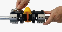
STEP 3.
- Mount other half of the element to hubs.
- Tighten all capscrews to the recommended capscrew torques for proper installation below.

- Aboves shown spacer type coupling installation; the same procedure applies for the standard type coupling.
-Helpful tip!
If the capscrew holes in the element do not line up with the hubs properly due to equipment misalignment, please rotate the shafts as you can install each capscrew. For lager couplings, first install the capscrew that is positioned in the center of the half element.
-Helpful tip!
If the capscrew holes in the element do not line up with the hubs properly due to equipment misalignment, please rotate the shafts as you can install each capscrew. For lager couplings, first install the capscrew that is positioned in the center of the half element.
Recommended capscrew torques for proper installation
| Coupling Size | Bolt Size | Torque | |
|---|---|---|---|
| Nm | in lb | ||
| F-110 | M8 | 27 | 240 |
| F-125 | M8 | 27 | 240 |
| F-130 | M8 | 27 | 240 |
| F-150 | M10 | 53 | 468 |
| F-170 | M10 | 53 | 468 |
| F-190 | M10 | 53 | 468 |
| F-215 | M10 | 53 | 468 |
| F-245 | M10 | 53 | 468 |
| F-290 | M12 | 92 | 816 |
| F-365 | M14 | 158 | 1,404 |
| F-425 | M14 | 158 | 1,404 |
| F-460 | M14 | 158 | 1,404 |
Note
- A bolt having the highest tension should be used.
- Locktitle as an adhesive should be used.
- A bolt should never be used twise.
- Never treat a bolt with oil.